

Industrial pressure systems require a stable and long-distance signal. This is why many pressure transmitters use a 4–20 mA output [1][2].
The signal is suitable for use in process systems, plants, and factories where electrical noise is present. It also allows systems to detect faults and read the pressure easily [2][3]. A second advantage is the ability to transmit power and data on two wires.
This article describes the reasons for the continued viability of 4–20 mA as a pressure measurement system in industry.
Key Highlights:
- Know the reasons for the use of 4-20mA in industrial pressure transmitters.
- Understand how a pressure signal is translated to a current signal.
- Discuss the advantages of 4–20 mA, such as long-distance transmission and fault detection.
- Make comparisons between 4-20mA, voltage, and digital output signals.
- Learn about important considerations for choosing a 4–20 mA pressure transmitter.
What Is a 4–20 mA Signal in Pressure Measurement?
A pressure transmitter converts a pressure measurement into an electrical signal. The current in a 4 – 20 mA system increases with increasing pressure [1][5]. The control system subsequently transforms that current back into a pressure value.
Converting Pressure into Current
The 4 mA point is at the bottom of the set pressure range. The upper end is 20 mA (the 20 mA point). Any values in between these points indicate pressure proportional to the values.
For instance, a transmitter that has a range of 0 to 10 bar. If the signal is 4mA, then the pressure is 0 bar. The middle of the range is indicated if the signal is 12mA, which corresponds to 5 bar. The pressure is 10 bar at a current of 20 mA.
Use this formula to calculate the pressure:
Pressure = Lower range value + (Measured current – 4mA) / 16mA × Pressure span
The 16 mA is calculated as 20 mA – 4 mA.
To ensure the signal does not cross the zero line, it is started at 4 mA.
The initial start-up current of 4 mA is called a live zero [2][3]. It indicates whether the transmitter is powered or if the loop is powered. A lower current reading might indicate loss of power, broken wiring, or other fault in the loop [3].
The 4 mA current can also power many two-wire pressure transmitters [6][8]. This can enable the same pair of wires to be used for power and the pressure signal.
Six Reasons 4–20 mA Works Well in Industrial Pressure Systems
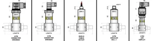
The 4-20 mA signal is widely used because it is a solution to some of the issues faced in the industrial world. Pressure transmitters are commonly placed outside of control rooms. They may also be close to machinery, such as motors and pumps, which can cause electrical disturbance. A current loop is an economical and reliable way of transmitting a pressure signal in these conditions.
1) Reliable Transmission Over Long Cable Runs
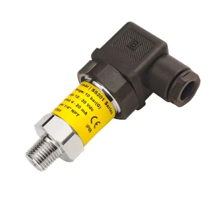
A significant advantage of 4–20 mA is that it can operate effectively over long distances [2][6]. Many pressure transmitters are located in remote areas of a plant, such as pipelines, storage tanks, or pump stations.
A current loop uses the current flow in the circuit as a signal. Changes in cable resistance may result in voltage loss, but the measured current value is not affected [6].
However, this does not mean that cable resistance is unimportant. The power supply voltage should be sufficient for the transmitter, cables, and receiving device [6][8]. The total resistance may become excessively high, which can cause the transmitter to function improperly.
This compromise allows 4–20 mA to be used in many industrial systems where pressure measurements must communicate between the field and a control panel.
2) Better Resistance to Industrial Electrical Noise
Electrical noise is frequently found at industrial locations due to equipment producing it. Weak electrical signals can be influenced by the presence of Power cables, switching devices, variable frequency drives, and motors.
This type of interference has less effect on a 4-20 mA current signal than many voltage-based signals [2][6]. This helps to keep the pressure reading more stable in challenging environments.
However, the signal is not completely protected from noise. Good wiring practices are still important. Proper cable selection, grounding, shielding, and cable routing reduce possible signal problems [8].

3) Live Zero Helps Detect Faults
The 4 mA starting point is a valuable asset in industrial monitoring. Also, the control system can better detect abnormal conditions because the current is not zero when the pressure is zero [2] [3].
A transmitter, for instance, operating within its normal range can produce an output of 4 mA to 20 mA. If the current is near 0 mA, it could indicate power loss, wound wiring, or a transmitter problem.
Some intelligent transmitters will also indicate faults by sending out signals outside of the normal measurement range [3]. The fault behavior varies depending on the transmitter design and configuration.
4) Two Wires Can Carry Power and Signal

Two-wire loop design is used in many types of industrial pressure transmitters [6][8]. The same two wires are used to send electrical power to the transmitter and to return the measurement signal to the control system [6].
This minimizes field wiring when installing. It also simplifies system design for many applications.
The transmitter must be supplied with the proper voltage to run. The total loop design should be reviewed by the engineer before installation.
5) Works with Common Industrial Control Systems
Another reason for the wide use of 4–20 mA is compatibility. Many PLCs, DCS systems, and monitoring devices use standard current inputs.
This enables the use of pressure transmitters of various brands with existing control systems. The control system can then translate the current value into bar, psi, kPa, or other pressure units.
This is a typical solution that minimizes installation issues and simplifies maintenance for many industries.
6) Simple Testing and Maintenance
A 4–20 mA loop can also be easily tested. Loop calibrators and measurement tools can be employed to determine if the transmitter is functioning properly [7].
The signal range is straightforward. A technician can easily test if the loop is giving the desired current value.
Modern systems can also incorporate digital communication, which can be achieved using the HART technology [4][5]. This provides the possibility to share other information – for example, the status of the device or configuration data – without losing the traditional 4–20 mA signal.
How Does 4–20 mA Compare With Other Pressure Sensor Outputs?
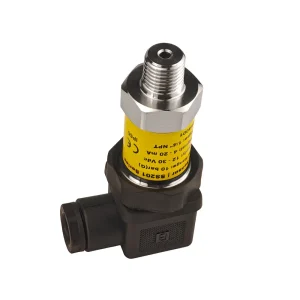
4-20mA is commonly used, but is not the only output available to measure pressure. For some applications, engineers can also select voltage output or digital communication systems.
Depending on the amount of information the system requires, installation conditions, control system requirements, and cable distance, the right choice can be made.
1) 4–20 mA Compared With 0–10 V or 0–5 V Outputs
In some automation systems, the output is in the form of voltage, particularly if the sensor is near the control unit. They are commonly found in small systems, test equipment, and machines.
However, long distances can cause voltage signals to be influenced by cable resistance and electrical interference. The measured value is affected by a slight voltage change due to wiring conditions.
A 4–20 mA signal is typically better suited for an industrial pressure measurement application and is generally used remotely, since the current itself is controlled in the loop. It is more appropriate for large plants, pipelines, and equipment, where the sensors are located a long distance from the controller.
This does NOT indicate that voltage outputs are too bad. They can give correct results for short connections with the correct input system. The selection should be made considering the whole application.
2) 4–20 mA Compared With 0–20 mA
In both of these, 4–20 mA and 0–20 mA, the current signal is used to carry measurement information. The only difference is where they begin.
Zero current can be the lowest measurement value in a 0 – 20 mA system. It can also indicate a loss of power in the loop or a wiring issue.
This is because a 4–20 mA system can ignore this problem by taking it as its lowest normal signal of 4 mA. This additional current range is beneficial because it provides the control system with a better means to determine if there are any potential issues.
This is why 4–20 mA became a popular option for many industrial measurement systems.
3) 4–20 mA Compared With Digital Communication
Digital communication systems can provide more information than a basic analog signal. They can transmit the status of the device, its configuration, and other measurement data.
But for many industrial plants, simplicity, familiarity and existing equipment are reasons for continuing to use 4–20 mA. The main pressure value is provided by a basic current loop, without the need for a more advanced communication network.
Technologies like HART blend both of these approaches. They enable a transmitter to maintain the primary pressure signal on the 4-20mA loop, as well as supply digital data.
Analog and digital communication depend on the system’s requirements. A simple pressure monitoring point may only require a standard current signal. Digital features are worth considering for a larger process system.
Pressure Sensor Output Comparison
| Output | Best suited for | Main limit |
| 4–20 mA | Long cable runs and industrial plants | Carries limited data |
| Voltage | Short cable runs and small machines | More affected by cable resistance |
| Digital | Systems that need extra device data | Requires compatible equipment |
What Conditions and Limitations Should Be Considered?

The 4-20 mA system is easy and reliable. It must still be properly designed and installed, though. The transmitter, power supply, cables, and control system need to function properly together.
1) Calculate the Complete Loop Voltage Budget
A pressure transmitter is not a stand-alone device. There are several parts to a complete current loop. These can include the transmitter, cables, PLC input, safety barriers, and other devices.
Some of the power supply voltage is utilized in each section. The voltage available must be sufficient for the entire circuit.
Cable length is an important factor. Resistance is greater in longer cables. This results in a greater voltage drop in the loop.
The transmitter can produce the proper output signal if the available voltage is not too low. This may cause erroneous readings or erratic operation.
The engineers verify total loop resistance before installation. It’s compared with the transmitter requirements. Always follow the manufacturer’s instructions.
Each transmitter will have a specific operating range. No one value is suitable for all applications.
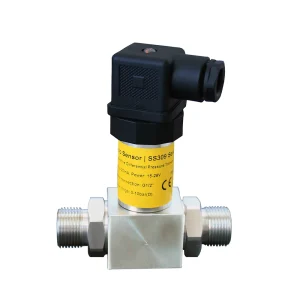
2) Wiring, Shielding, and Grounding Still Matter
A 4-20mA signal is good for industrial conditions. But good wiring is still important.
An inadequate connection can cause signal issues. Damaged cables, loose connections, and dampness can also impact performance.
Motors, power cables, and other equipment in industrial locations are sources of electrical interference. These effects are minimized with proper cable selection and installation.
Shielded cables can be used in locations where there is a lot of electrical noise. Grounding methods should be in accordance with transmitter and system requirements.
Install a good loop that will allow the pressure transmitter to give good readings without drifting over time.
3) An Analog Loop Has Data Limits
A typical 4-20 mA loop transmits one measurement. This value is typically the pressure reading for a pressure transmitter.
It is a simple design, one of the reasons that many industries still use it. But it also has its drawbacks.
A simple current loop can transmit only small quantities of information. It cannot provide the same level of data as many digital communication systems.
Some applications require more information. They might need device status, remote settings, or advanced diagnostics.
In these instances, digital communication can be helpful. One example of this is HART communication. It maintains the traditional 4–20 mA signal and provides digital information.
This enables industries to adopt modern features without having to replace current analog systems.
Checks Before Powering the Loop
- Make sure that the 4-20 mA input is suitable for the control system.
- Test the power supply and overall loop resistance.
- Use the proper wiring and polarity.
- Don’t run signal cables in the vicinity of power cables and motors.
- Check all terminals for loose/damaged connections.
- Test the loop prior to normal operation.
Where Are 4–20 mA Signals Most Useful?
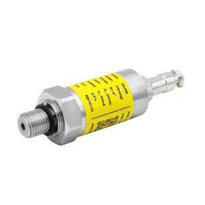
4–20 mA signals are used in many industrial applications. They are particularly well suited when pressure readings must be transmitted long distances and/or must withstand harsh environments.
The signal is used in many industrial fields including water treatment, manufacturing, energy, and process automation. Often these industries require pressure data from equipment that is a great distance from the main control system.
1) Water and Pumping Systems
Pressure transmitters are commonly used in water systems to monitor pumps, pipelines, and storage tanks.
A pump station can be a considerable distance from the control room. This distance can be bridged with a 4–20 mA signal, which helps transmit pressure data stably.
Monitoring can be done with the signal to:
- Pump pressure
- Pipeline pressure
- Temperature and barometric pressure with hydrostatic pressure as a reference point
- Filter pressure changes
This enables operators to understand what is happening in the system and catch problems early.
2) Manufacturing and Industrial Machines
Many factories have hydraulic or pneumatic systems on their machines. Pressure monitoring is needed for the safe and efficient operation of these systems.
4-20mA output pressure transmitters are used for the measurement of hydraulic pressure, air pressure, as well as process pressure. The signal can be directly connected to PLC systems that control machine operation.
The high performance of current loops is useful where motors and electrical equipment are in proximity.
3) Process and Energy Industries
Accurate pressure measurement is essential to industries like oil and gas, chemical processing and power generation.
In such situations, the transmitters are frequently placed in hard-to-reach places. They can also be used under conditions of temperature changes, vibration, and electrical noise.
A standard 4–20 mA signal offers a straightforward way of connecting field instruments with control systems.
4) OEM Equipment and Automation Systems
Machine manufacturers commonly use 4–20 mA outputs as they are compatible with typical industrial controllers.
Machine builders can use pressure sensors in various systems without needing to develop a custom communication method.
This simplifies installation for customers who are already using PLCs or automation equipment.
The ideal output mode always depends on the application. Always consider conditions like distance, system design, and data requirements when selecting a pressure transmitter.
How to Decide If 4–20 mA Is Right for Your Application
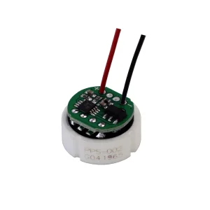
When selecting pressure transmitters, it is important to choose the appropriate output signal. A 4–20 mA output is a good option for many industrial systems. But that may not be the best course of action in all cases.
The first step is to determine what the application needs. Engineers should consider the distance the signal must travel, the control system that will receive the signal, and the kind of information needed [2][6].
When choosing a 4–20 mA pressure transmitter, keep the following in mind.
1) Check Control System Compatibility
The receiving device must have a 4- 20 mA input. This signal is normally provided on the analog input channels of most industrial PLCs and DCS systems. The transmitter and control system should also be compatible.
2) Check the Power Supply and Loop Design
The power supply must provide adequate power to the circuit. If the cables are longer, there can be more resistance. This may result in a lower voltage available at the transmitter.
The correct loop calculation can help avoid signal issues following installation.
3) Consider the Installation Environment
The choice also depends on the pressure transmitter’s location.
The advantage of a 4-20mA signal is for situations where the cable runs for long distances, or there is electrical equipment that can cause interference. It is generally used in factories, plants, and outdoor installations.
But the transmitter has to meet other criteria. These can include temperature restrictions, pressure range, process connection, and dust or water protection.
4) Decide If Extra Data Is Needed
The main pressure value is sent using a basic 4-20mA signal. This should suffice for many monitoring and control applications.
Some systems require additional information. They might need to know the status of the device, remote configuration, or advanced diagnostics [4][5].
A digital-communicating transmitter might be a better option in such instances. One possibility is the use of HART, which provides digital capabilities and retains the 4–20 mA signal.
5) Use a Complete Selection Approach
One part of selecting pressure transmitters is the output signal. Other factors to consider are accuracy, pressure range, media compatibility, and operating conditions.
4- 20 mA is still widely used because it is a simple and proven method for industrial pressure measurement. If the system is designed to meet the requirements, it can perform well for many years when its requirements match its strength.
FAQs:
1) Does a 4–20 mA pressure transmitter always need a 24 V power supply?
24 V DC pressure transmitters are used in many industrial pressure measurement applications. However, the amount of power required depends on the transmitter design. The power supply should be sufficient to power the entire circuit. This includes the transmitter, cable resistance, and receiving equipment. Please read the manufacturer’s instructions carefully before installing. [8]
2) How far can a 4–20 mA pressure signal travel?
For each 4–20 mA system, there are no set distance limits. The distance may vary depending on cable size, loop resistance, supply voltage, and transmitter requirements. A properly designed current loop will accommodate long cable runs. For each application, engineers must run the full loop calculation. [2][6]
3) Can multiple pressure transmitters share one PLC input?
A typical 4–20 mA connection is used for one transmitter and one input channel. Normally, each pressure transmitter comes with its own loop connection. This enables the control system to maintain independent control over each pressure point. Some digital communications systems can support multiple devices on a single network. This, however, is not typical of an analog 4–20 mA loop.
4) Can a 4–20 mA signal be changed into a voltage signal?
Yes, the 4-20mA signal can be converted to a voltage signal if the appropriate conversion is used. This is useful for a control system designed to receive a voltage input rather than a current input. The conversion method has to be in accordance with the system conditions. Measurement accuracy may be affected by incorrect conversion.
5) Does 0 mA always mean a broken wire?
No. If the reading is 0 mA, no current is flowing in the loop – this can have many reasons. This may be due to loss of power, wiring, faulty transmitter, or other loop problems. Before identifying the fault, check the transmitter manual and system design. [3]
6) Is 4–20 mA more accurate than a voltage output?
The type of output does not determine the measurement accuracy. Accuracy is limited by transmitter design, sensor quality, sensor calibration, installation, and operating conditions. A 4-20mA signal can be more desirable due to its ability to function well in industrial applications, particularly for more distant applications.
7) Can HART communication work with a 4–20 mA signal?
Yes. HART communication can work together with a traditional 4–20 mA loop. The 4–20 mA signal represents the primary measurement. HART adds digital information, such as device settings and diagnostic data. This enables industries to use extra features without needing to replace the existing current loop system. [4][5]
8) Is a 4–20 mA loop automatically safe for hazardous areas?
No. A standard 4-20mA loop is not necessarily fit for hazardous areas. Potential hazardous areas must be properly certified and use appropriate equipment. This can involve approved transmitters, barriers, and installation techniques. All of the above must comply with the necessary safety requirements.
Conclusion:
Even with so many advancements in the field, 4-20 mA is still widely used as a signal for industrial pressure measurement due to its simple and proven means of transmitting information from the field to the control system. It is ideal for many industrial applications due to its capability of long cable runs, minimizing electrical noise effects and fault detection.
The signal is also compatible with other PLC and DCS systems. Its design is simple, making installation, testing, and maintenance easier for engineers/technicians.
But when choosing a pressure transmitter, there are more factors to consider than just the output signal.
Digital communication is becoming increasingly common in industrial automation. Despite this, 4-20mA still has its uses in the world and is still a practical and reliable solution for many pressure measurement applications.
Need a strong pressure measurement solution for your industrial application? Discover Sendo Sensor’s offerings in pressure sensors and transmitters that perform accurately and reliably in challenging conditions.
Check out Sendo Sensor’s technical blog for more information on industrial pressure measurement, sensor selection, and automation solutions.
References:
1) International Electrotechnical Commission (IEC) IEC 60381-1: Analogue Signals for Process Control Systems – Part 1: Direct Current Signals
2) Baker, N. (2017). Industrial Instrumentation and Control Systems: Current Loop Technology and Applications. ISA (International Society of Automation) Technical Publications.
3) NAMUR NE 43: Standardization of the Signal Level for Failure Information of Digital Transmitters
4) FieldComm Group HART Technology Explained
5) HART Communication Foundation. HART Communication Protocol: A Technical Overview. FieldComm Group Technical Documentation.
6) Analog Devices High Performance, High Accuracy 4–20 mA Current Loop Transmitter Design
7) Fluke What Is a 4–20 mA Current Loop?
8) Lipták, B. G. (Ed.). (2003). Instrument Engineers’ Handbook: Process Measurement and Analysis. 4th Edition. CRC Press.